By Eleanor Oldham, Senior Geophysicist
Creating robust well to seismic ties is a crucial yet unloved workflow which must be performed at the start of any seismic interpretation project. The value added to a project by having a confident set of well-seismic ties cannot be understated. The best stratigraphic interpretation in the world is meaningless if your carefully picked formations line up with the wrong seismic reflectors. The flow chart below gives an example of a typical workflow which could be invalidated if the well-seismic ties are incorrect.
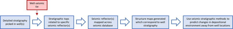
Evidently, the consequences of bad well-seismic ties can be devastating for a project: From misinterpretation of depositional environments, to wells drilled in the wrong place. I would say that’s reason enough to invest in high-quality well-seismic ties!
I’ve got a VSP/checkshot survey – can’t I just use that?
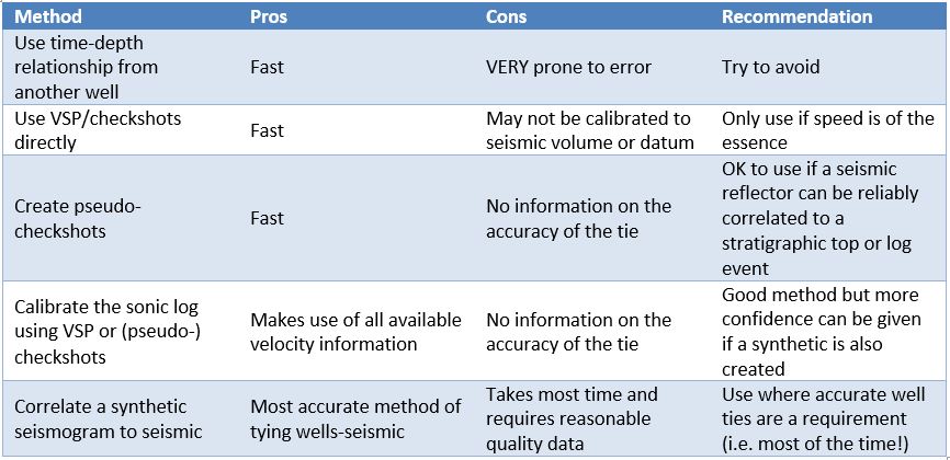
If you’re in a hurry, there’s no problem with using time-depth pairs directly from a VSP/checkshot survey provided you take a couple of QC steps first. As a minimum you should look at the interval velocities to make sure there are no spurious points hidden in your data. I would caution against applying a VSP from one well to other wells in the area unless the stratigraphy is known to be very homogenous.
I don’t have any checkshot information – what can I do?
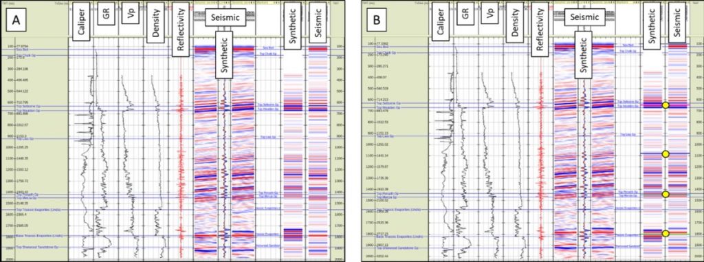
I recommend creating a couple of pseudo-checkshots as a starting point. A pseudo-checkshot is a time-depth pair which takes its time from a characteristic seismic event and depth from the (hopefully!) corresponding log event seen in the well. Figure 2A shows a well I quickly tied to seismic using pseudo-checkshots. If speed is of the essence then you could leave the well-seismic tie here, but be warned, you have no independent verification that your chosen pseudo-checkshots are in the right place.
A highly recommended follow up step is to use the sonic and density logs to create a synthetic trace which you can compare to the seismic. If you think some of the reflectors look misaligned between synthetic and seismic, you can “pin” them to where you think they should be by interpreting stretch/squeeze pairs (Figure 1). Figure 2B shows my example well-seismic tie after synthetic-seismic correlation. It’s scary how much the formation tops move between the two well-seismic tie methods shown in Figure 2 – this could change the way you map the seismic!
I’ve got an embarrassment of high-quality data – how can I get the most out of it?
If you’re fortunate enough to have good quality log, VSP and seismic data you can take the synthetic-seismic correlation process one step further and extract a quantitative wavelet from the seismic. A quantitative wavelet can provide accurate information about the frequency and phase of the seismic – which might not be as zero-phase as you thought!
If you have seismic angle stacks and a shear sonic log you can repeat the well-seismic tie process for each angle range and extract quantitative wavelets for each. This sort of detailed information is highly valuable if you want to carry out seismic inversion.
Well to seismic ties… Always worth the bother!
Producing a reliable set of well to seismic ties is a crucial first step for any seismic interpretation project. Sadly, there’s little glory in producing a high quality well-seismic tie but getting it wrong can have devastating (not to mention expensive) consequences. If you’ve got some troublesome well-seismic lines why not drop us a line…
Example well-seismic tie images contain information provided by the Oil and Gas Authority and/or other third parties.
Merlin use IHS Markit Kingdom and Ikon’s RokDoc software to carry out well to seismic ties
